This was my first project ever with an Arduino, which I finally figured out fall semester of 2014. I had found many tutorials on building a simple vu meter (measures volume of music and displays it in a led array), but many were buggy and I didn't know a lot of code or have any experience with electronics so I took a while to figure it out. Here is a quick explanation of how I wired it together and how the code works:
(Special thanks to Zero the Geek from tumblr who helped me wire up the Arduino correctly and James Newbould who wrote the original code)
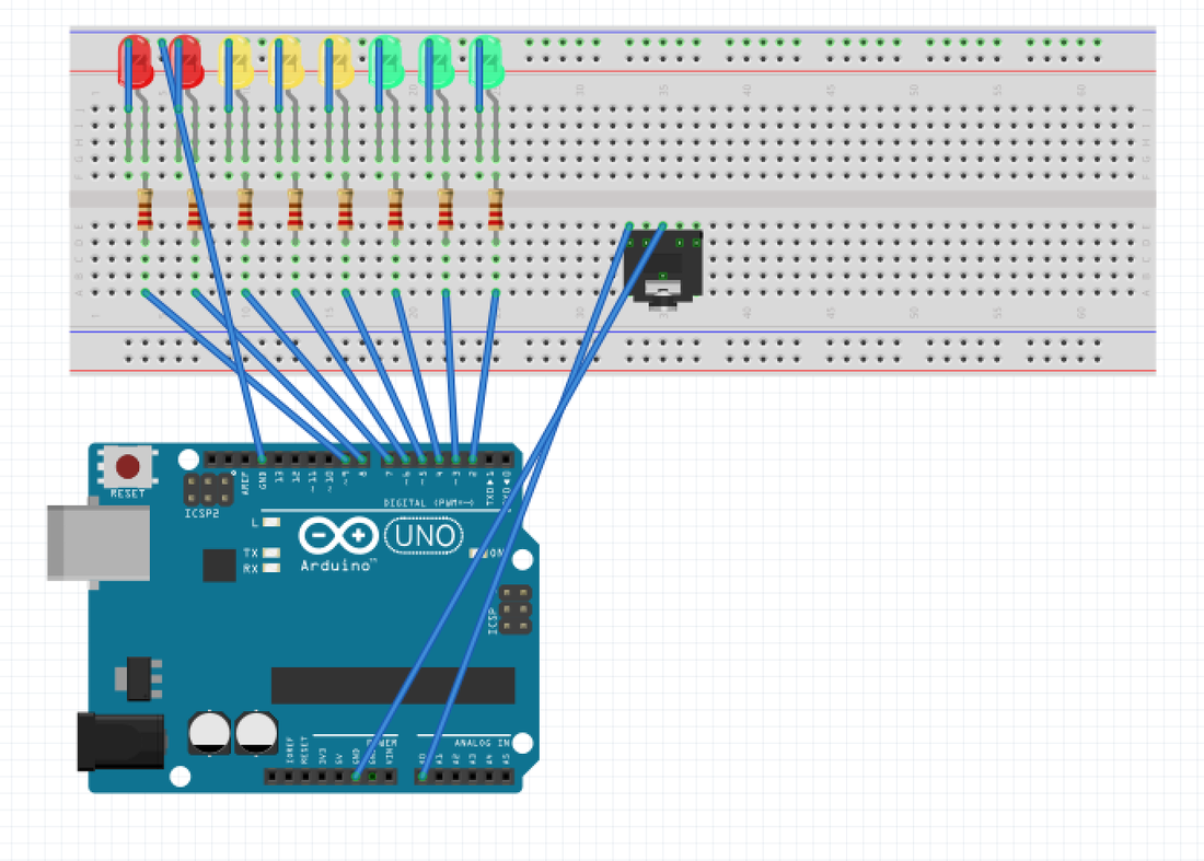
First lets begin with the Arduino wiring!
I built an array of red, yellow, and green LEDs. For every LED, I connected with a small wire the cathodes (small legs) to the ground pin of the Arduino. For the anode (long leg) of every LED, I first connected a 330 Ohm resistor between the anode and a wire that will connect every LED to a pin on the Arduino. The Arduino provides 5 volts, so a 330 ohm resistor is enough to protect the LED bulb from burning out. I plugged the 8 LEDs to pins 2-9 in this example.
Next, we are going to be using the signal received from a breadboard audio jack to instruct the Arduino which lights to turn on according to a voltage level. We connect the audio jack ground pin (the middle pin on the jack) to the other ground pin on the Arduino and the left input channel (left pin on jack) to an analog pin on the Arduino. This wiring will complete our circuit.
Now to the code part:
(Special thanks to Zero the Geek from tumblr who helped me wire up the Arduino correctly and James Newbould who wrote the original code)
First lets begin with the Arduino wiring!
I built an array of red, yellow, and green LEDs. For every LED, I connected with a small wire the cathodes (small legs) to the ground pin of the Arduino. For the anode (long leg) of every LED, I first connected a 330 Ohm resistor between the anode and a wire that will connect every LED to a pin on the Arduino. The Arduino provides 5 volts, so a 330 ohm resistor is enough to protect the LED bulb from burning out. I plugged the 8 LEDs to pins 2-9 in this example.
Next, we are going to be using the signal received from a breadboard audio jack to instruct the Arduino which lights to turn on according to a voltage level. We connect the audio jack ground pin (the middle pin on the jack) to the other ground pin on the Arduino and the left input channel (left pin on jack) to an analog pin on the Arduino. This wiring will complete our circuit.
Now to the code part:
 //Led VU Meter Example
// Version 1.0
// Written by James Newbould
// Edited a little by Zero the Geek 08-13-2013

int led[8] = { 2, 3, 4, 5, 6, 7, 8, 9}; // Assign the pins for the leds
int leftChannel = 0; // left channel input
int left, i;

void setup()
{
for (i = 0; i < 8; i++) // Tell the arduino that the leds are digital outputs
pinMode(led[i], OUTPUT);
//Serial.begin(9600); // Uncomment to enable troubleshooting over serial.
}

void loop()
{
left = analogRead(leftChannel); // read the left channel

// Serial.println(left); // uncomment to check the raw input.

left = left / 50 ; // adjusts the sensitivity

// Serial.println(left); // uncomment to check the modified input.
// left = 1500; // uncomment to test all leds light.
//left = 0; // uncomment to check the leds are not lit when the input is 0.

if (left == 0) // if the volume is 0 then turn off all leds

{

for(i = 0; i < 8; i++)
{
digitalWrite(led[i], LOW);
}

}

else

{
for (i = 0; i < left; i++) // turn on the leds up to the volume level
{

digitalWrite(led[i], HIGH);

}

for(i = i; i < 8; i++) // turn off the leds above the voltage level
{

digitalWrite(led[i], LOW);

}

}

}
To start we declare our variables: the LED array and the analog pin we picked (in this case pin 0).
In the setup loop, we declare that all the digital LED pins are our outputs. This will always be the case (LEDs will always be our outputs) so we keep this in the setup portion of the code. For our ongoing loop, we tell the Arduino that it will read in the signal it receives from the analog pin we declared earlier. Then we declare the sensitivity of how much voltage the LEDs will receive. You can change the ratio depending on how good is the amplifier you are connecting into the jack. We add an if clause to make sure all LED are turned off when we are receiving no signal from the audio jack. Now we create a for loop that constantly checks the voltage level and lights up a certain amount of LEDs depending on the voltage. The last for loop is used to shut off the LEDs above the voltage level.
Here is a video of my VU meter. Hope you like snoop!
(Note: I played the music on my computer separately since my phone would not play the music when it was plugged into the vu meter. If you want to hear the music and see the LED display at the same time, it is easier to use a small breadboard microphone to measure the voltage instead of an audio jack)

 RSS Feed
